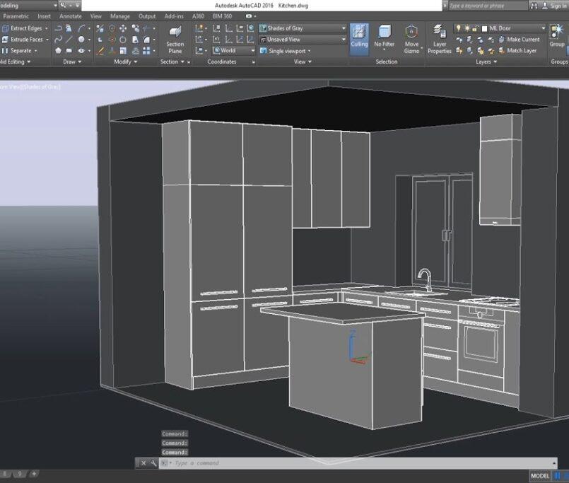


When creating precise and accurate drawings in AutoCAD, mastering the concept of scale factor is essential. The scale factor determines the relationship between real-life dimensions and their representation in the drawing, ensuring that your designs are both proportional and practical. In this comprehensive guide, we’ll delve into the intricacies of the AutoCAD scale factor, its calculation, application, and best practices to elevate your drafting skills.
What is an AutoCAD Scale Factor?
In AutoCAD Software, the scale factor is a numerical representation of the size ratio between an object’s real-life dimensions and its depiction in the drawing. Typically expressed as a ratio or fraction, a scale factor of 1:1 signifies a full-size representation, mirroring real-life dimensions accurately. However, most drawings necessitate scaling down due to spatial limitations, making scale factors indispensable for achieving the desired drawing size while retaining precision.
Calculating and Applying Scale Factors in AutoCAD
AutoCAD offers several methods for setting scale factors, each tailored to suit different design requirements:
- Using the ‘SCALE’ Command: This method enables you to specify a reference length and input the desired size on the drawing, facilitating precise scaling adjustments.
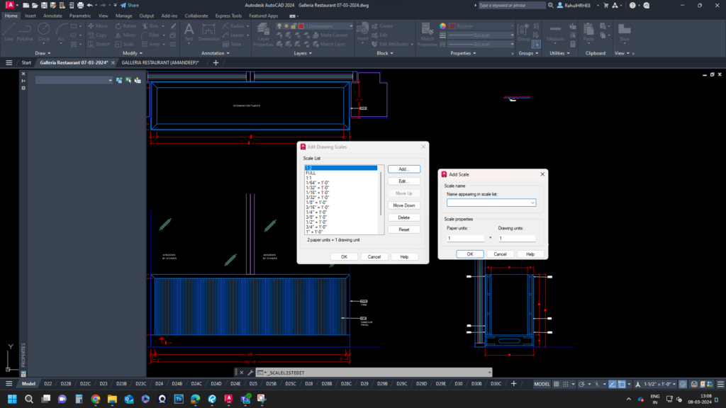
- Preset Scale Factors: AutoCAD provides preset scale factors such as 1/2xp (half size) or 2xp (double size) through the ‘SCALELISTEDIT’ command, streamlining the scaling process for efficient drafting.
- Global vs. Individual Application: Scale factors can be applied globally to the entire drawing or individually to specific elements, offering flexibility and accuracy in design implementation.
Methods of Specifying Scale Factors in AutoCAD
AutoCAD offers diverse methods for specifying scale factors, tailored to suit various design scenarios:
- Absolute Scale Factor: Enter a specific value for the scale factor (e.g., 1:2 or 3/4xp) to achieve precise and accurate scaling across all elements.
- Relative Scale Factor: Scale factor relative to a user-specified reference length, offering flexibility when working with irregularly sized objects.
- Fit Scale Factor: Utilize the ‘SCALE’ command with a scale factor of 0 to swiftly fit drawing elements within the desired size.
- Scale by Reference: Select a reference object and specify the desired size to calculate the scale factor automatically, ideal for maintaining specific ratios or proportions.
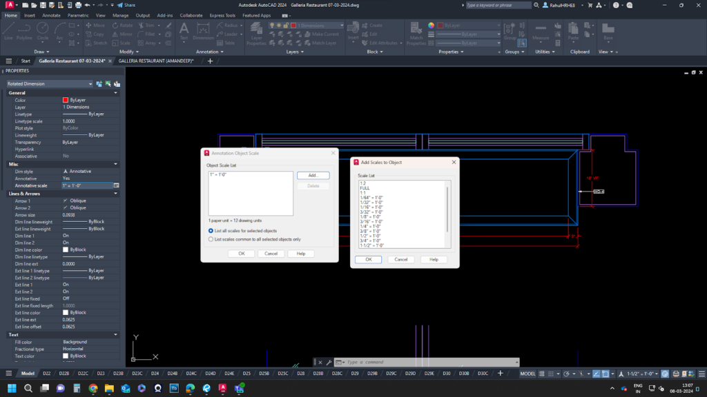
- Annotative Scale Factor: Apply scale factors to annotations like dimensions and text, ensuring consistent legibility irrespective of drawing size.
Importance of AutoCAD Scale Factor in Design
Understanding and utilizing scale factors correctly is paramount for producing accurate and professional drawings in AutoCAD. Scale factors ensure consistency, precision, and readability across drawings, minimizing errors and misinterpretations. Additionally, correctly setting scale factors is crucial for ensuring prints are to scale and align with the intended dimensions.
Understanding and utilizing scale factors correctly is paramount for producing accurate and professional drawings in AutoCAD. Scale factors ensure consistency, precision, and readability across drawings, minimizing errors and misinterpretations. Additionally, correctly setting scale factors is crucial for ensuring prints are to scale and align with the intended dimensions.
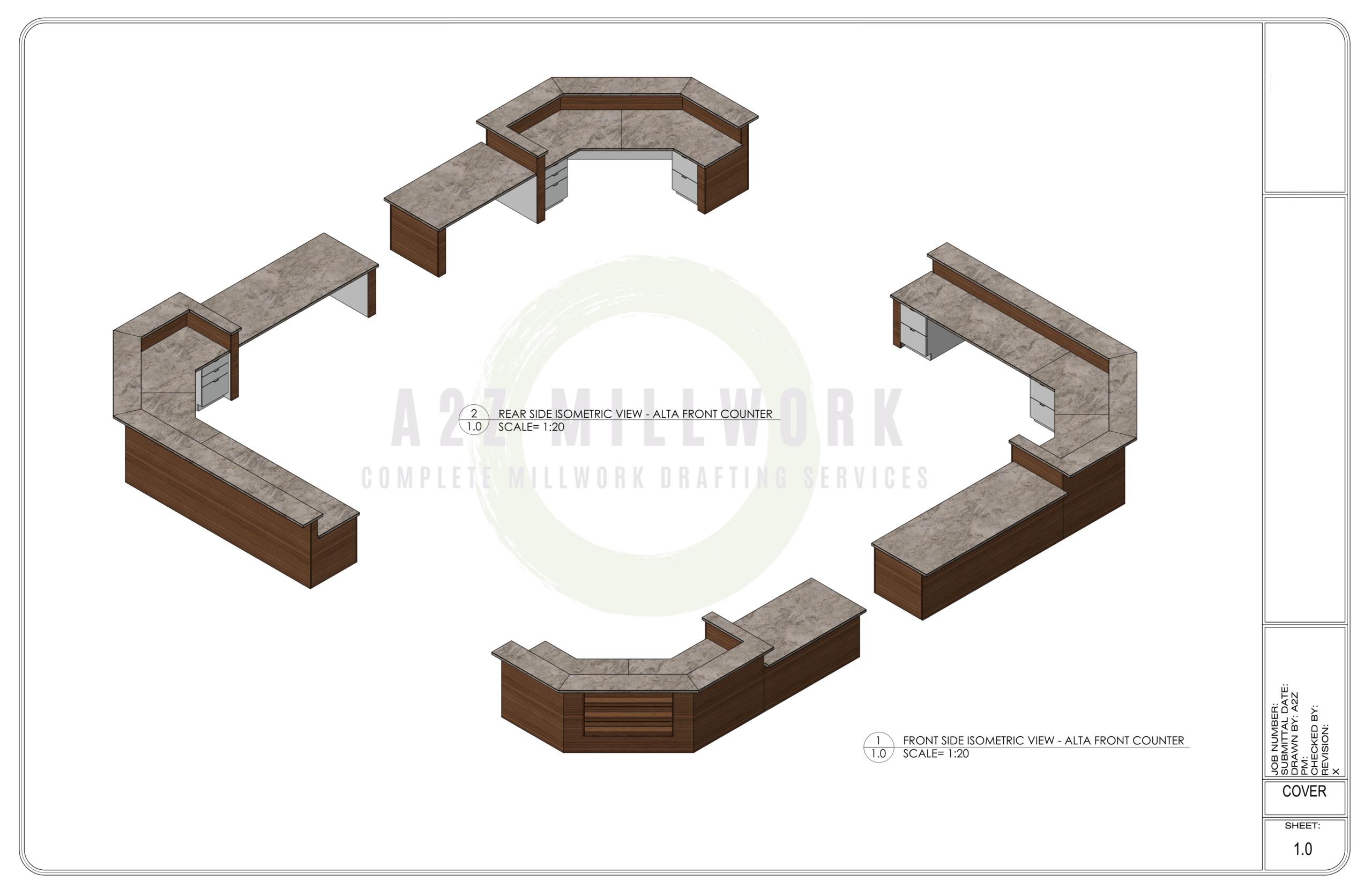
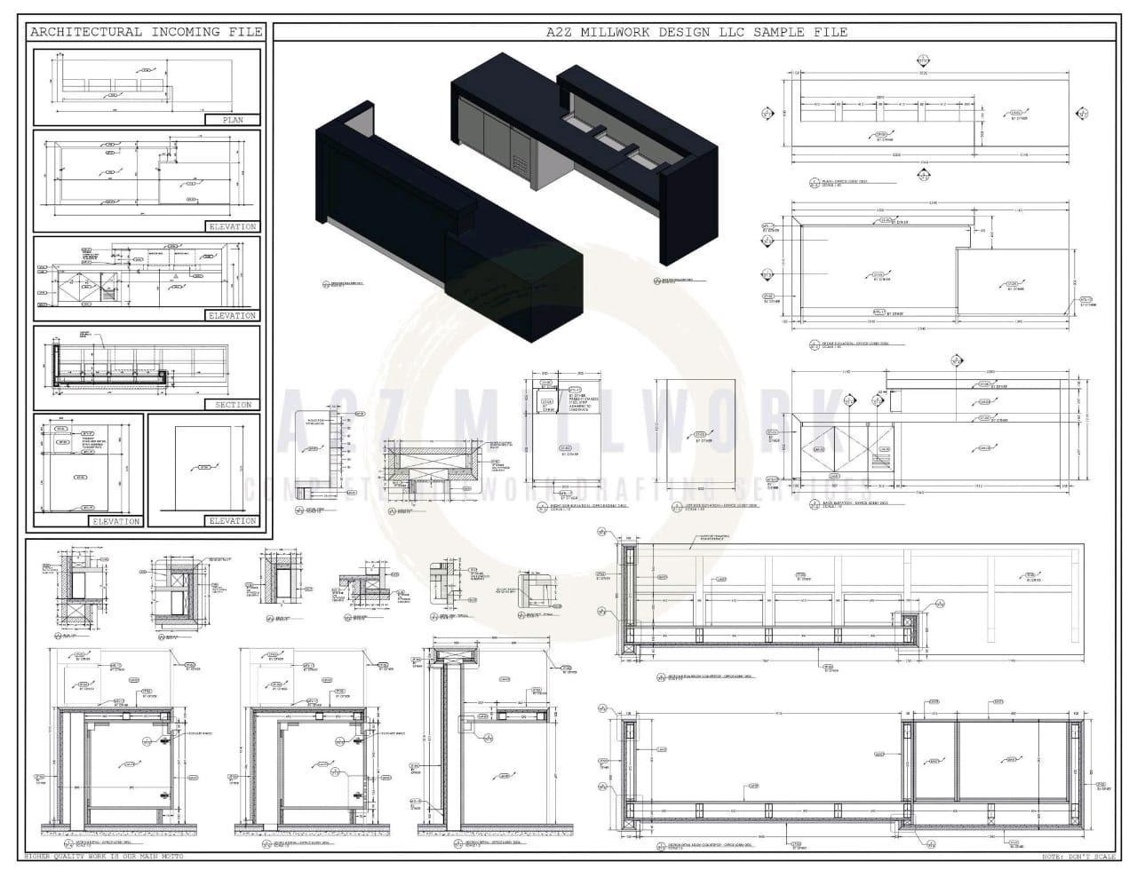
AUTOCAD SCALE FACTORS CHARTS
Two types of scale factor charts are commonly used in AutoCAD: the architectural and engineering scale charts. These charts provide a quick reference for commonly used scales, making choosing a suitable scale factor easier.
Architectural Scales
Drawing Scale | Scale Factor | Viewport Scale | Decimal Scale |
1/16″ = 1′-0″ | 192 | 1/192xp | .0625″ = 1′-0″ |
3/32″ = 1′-0″ | 128 | 1/128xp | .09375″ = 1′-0″ |
1/8″ = 1′-0″ | 96 | 1/96xp | .125″ = 1′-0″ |
3/16″ = 1′-0″ | 64 | 1/64xp | .1875″ = 1′-0″ |
1/4″ = 1′-0″ | 48 | 1/48xp | .25″ = 1′-0″ |
3/8″ = 1′-0″ | 32 | 1/32xp | .375″ = 1′-0″ |
1/2″ = 1′-0″ | 24 | 1/24xp | .50″ = 1′-0″ |
3/4″ = 1′-0″ | 16 | 1/16xp | .75″ = 1′-0″ |
1″ = 1′-0″ | 12 | 1/12xp | 1″ = 1′-0″ |
1 1/2″ = 1′-0″ | 8 | 1/8xp | 1.5″ = 1′-0″ |
3″ = 1′-0″ | 4 | 1/4xp | 3″ = 1′-0″ |
Engineering Scales
Drawing Scale | Scale Factor | Viewport Scale |
1″ = 10′-0″ | 120 | 1/120xp |
1″ = 20′-0″ | 240 | 1/240xp |
1″ = 30′-0″ | 360 | 1/360xp |
1″ = 40′-0″ | 480 | 1/480xp |
1″ = 50′-0″ | 600 | 1/600xp |
1″= 60′-0″ | 720 | 1/720xp |
1″ = 70′-0″ | 840 | 1/840xp |
1″ = 80′-0″ | 960 | 1/960xp |
1″ = 90′-0″ | 1080 | 1/1080xp |
1″ = 100′-0″ | 1200 | 1/1200xp |
Common Issues and Solutions
Several common challenges may arise when working with scale factors in AutoCAD, including unit mismatches, distorted elements, printing discrepancies, and human error. Adopting meticulous practices, verifying settings, and leveraging scale factor charts can mitigate these issues effectively.
Best Practices for Using Scale Factors in AutoCAD
To optimize the use of scale factors in AutoCAD and streamline your drafting process, adhere to these best practices:
– Familiarize yourself with different methods of specifying scale factors.
– Double-check settings and units to avoid errors.
– Utilize multiple scale factors for individual elements if needed.
– Refer to scale factor charts for quick reference.
– Regularly audit drawings for inconsistencies and rectify them promptly.
Mastering the AutoCAD scale factor is indispensable for precision drafting and ensuring the accuracy and professionalism of your designs. By embracing best practices and leveraging AutoCAD’s diverse scaling methods, you’ll elevate your drafting prowess and produce impeccable drawings tailored to your project requirements.