How We Drafted a 26-Foot Commercial Bar: Sheet by Sheet
By A2Z Team · · 7 min read · Shop Drawings
Most articles about millwork shop drawings tell you what they are. This one shows you.
Below is a walkthrough of a real shop drawing package our team produced for a commercial bar and bar back. It is the same 11-sheet PDF you can download from our millwork portfolio. If you are a millwork manufacturer or contractor deciding what complete shop drawings should look like before you hand a project to a drafting partner, this is the level of detail you should expect.
The project at a glance:
- Commercial bar, roughly 26 feet long (314" verified in field)
- Full-height back bar wall at 144" with display, storage, and equipment zones
- 11 sheets: 3D overview, dimensioned plan, six elevations, and seven construction sections
- Drawn to the architect's A-series references so every view ties back to the design intent
Sheet 1: The 3D Overview
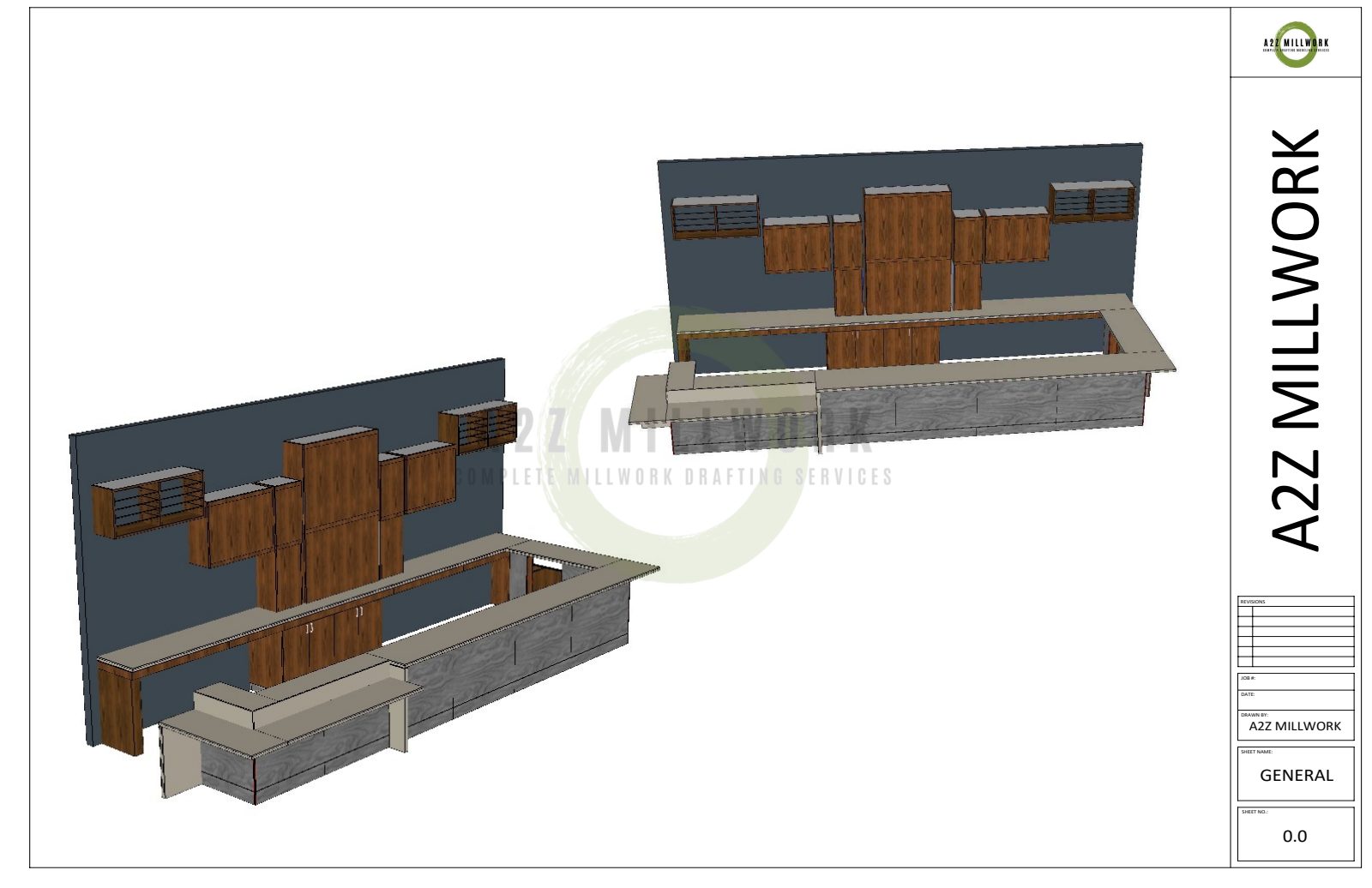
The package opens with two isometric 3D views of the complete bar and bar back. No dimensions, no callouts, just the massing.
This sheet exists for one reason: agreement before detail. The owner, architect, GC, and fabricator can all look at the same image and confirm "yes, that's what we're building" before anyone reads a single dimension. Catching a layout misunderstanding here costs nothing. Catching it after cutlists are generated costs materials, shop time, and schedule.
Sheet 2: The Plan View
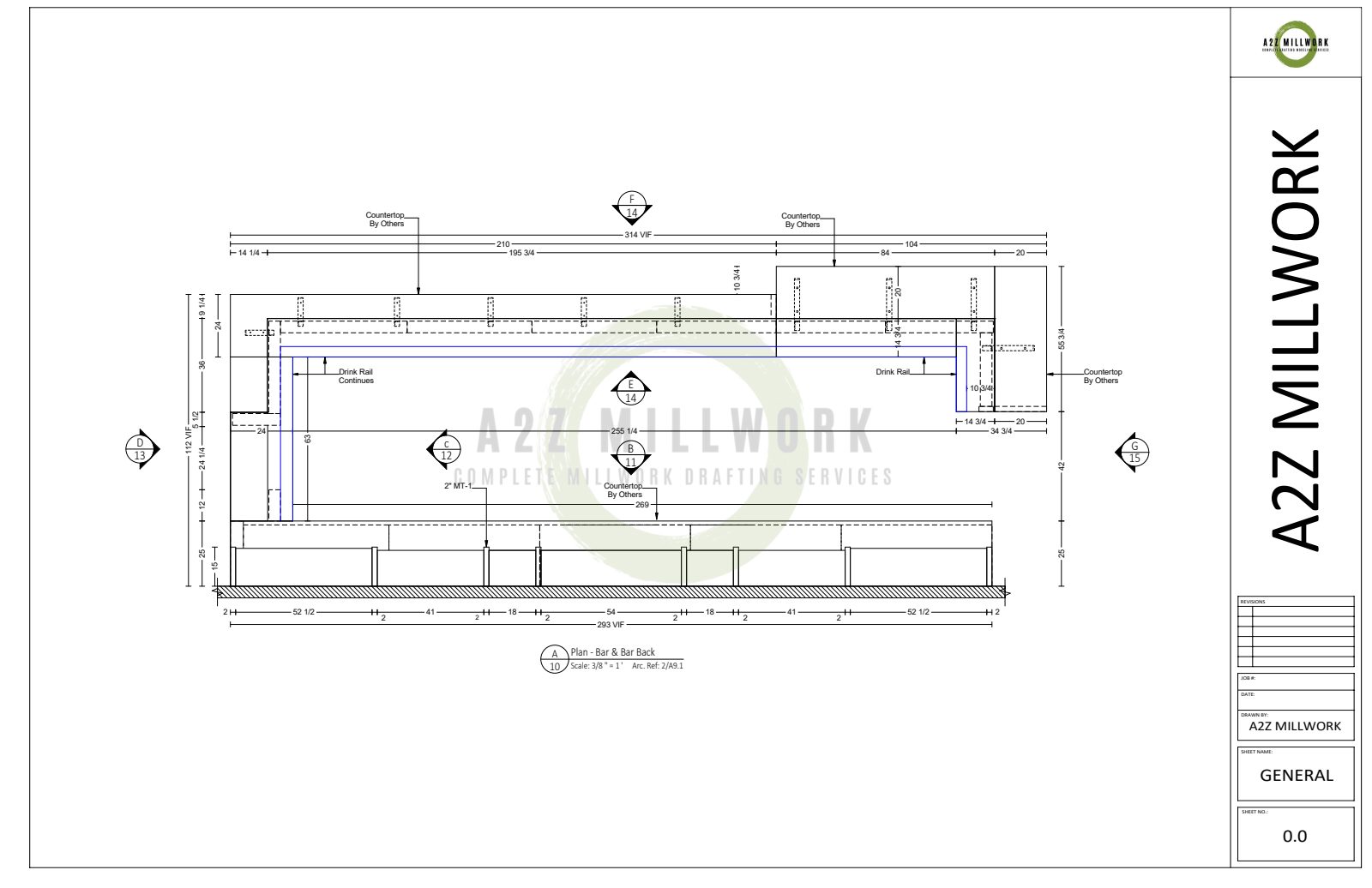
The plan view (drawn at 3/8" = 1') sets the footprint: the 314" main run, the 210" back wall run, and the drink rail that continues around the perimeter.
Two things on this sheet do the heavy lifting.
"Countertop By Others." The stone tops are not in the millwork scope, so the drawing says so, three separate times, exactly where the scope boundary sits. Vague scope boundaries are where job-site disputes are born. Explicit ones end the argument before it starts.
"VIF" means Verify In Field. The 314" and 293" dimensions carry VIF flags because walls in the real world are never exactly where the architectural set says they are. Flagging which dimensions must be field-verified before fabrication is the difference between casework that slides into place and casework that comes back on a truck.
Sheets 3 to 7: The Elevations
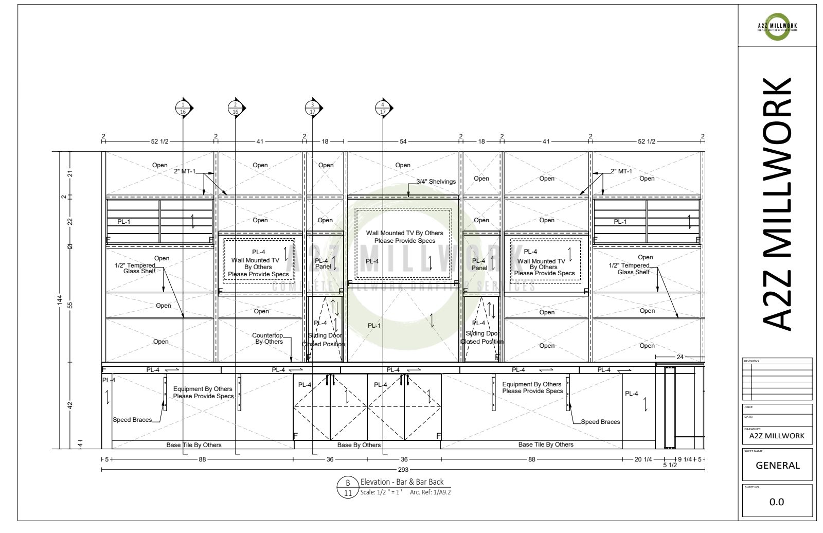
The main back bar elevation (1/2" = 1') reads like a map of the entire wall: 293" wide, 144" tall, broken into bays of 52½", 41", 18", and 54" with 2" reveals between them.
Every bay is annotated with what lives inside it:
- Sliding doors shown in closed position, with their open-position geometry detailed in the sections
- Wall-mounted TV zones marked "By Others, Please Provide Specs" so the electrician's scope and the millwork cutouts cannot drift apart
- ½" tempered glass shelves for display bays
- ¾" shelving with speed braces where spans need support
- A wine cabinet with racks integrated into the tower
- Material tags on every surface: PL-1 and PL-4 laminates, WD-1 wood veneer at the front bar, FRP-1 at the service side, black melamine interiors, and 2" MT-1 metal tube framing
The front bar elevations add the hospitality details that turn a counter into a bar: a continuous foot rail, purse hooks under the drink rail, USB ports on the guest side, and a waterfall end where the top returns to the floor.
Why so many elevations? Because a bar is viewed from four sides, and each side has a different audience. The guest side is about finishes and amenities. The service side is about equipment clearances: every equipment bay is drawn "Equipment By Others, Please Provide Specs" so refrigeration and beer systems land in openings that actually fit them.
Sheets 8 to 11: The Construction Sections
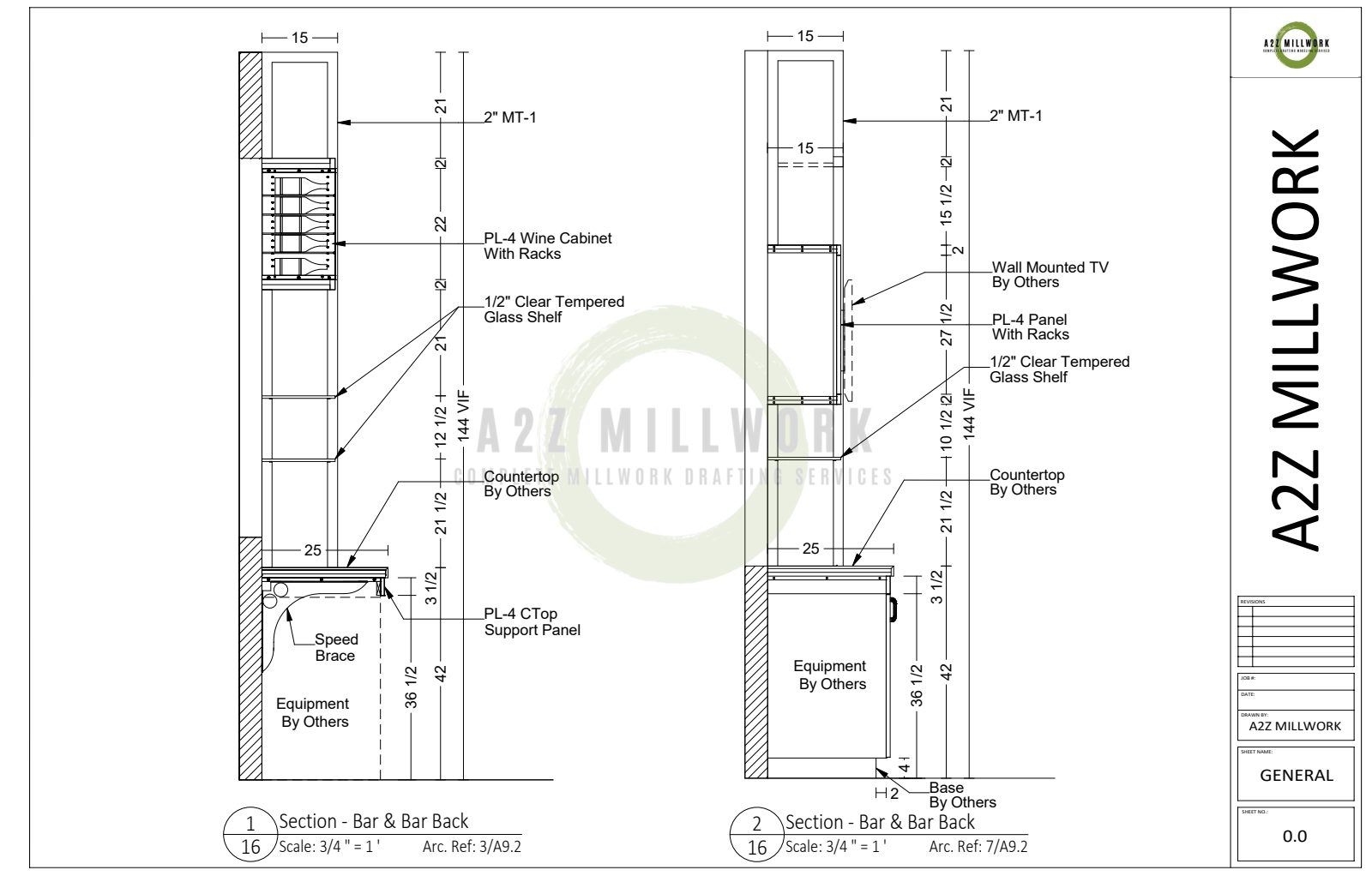
Elevations show what; sections show how. The package closes with seven construction sections drawn at 3/4" and 7/8" scale, large enough that a bench carpenter or CNC programmer can read exact assembly logic.
The sections resolve the questions the shop would otherwise phone in:
- How the 2" MT-1 metal tube frames the 144" tower, and where the PL-4 wine cabinet hangs inside it
- How the beer tap cabinet sits beyond the PL-1 open-back display cabinet
- How the drink rail is carried, with dimensioned support brackets and CFlat brackets at 42" transaction height
- Where the ¼" reveals land, so the shadow lines are consistent across the whole run
- How the transaction top (by others) meets the millwork below it
A section at this scale is the cheapest RFI you will ever answer, because it was answered before it was asked.
What This Package Prevents
- "By Others" tags with spec requests prevent scope disputes and missed coordination
- VIF flags on critical dimensions prevent casework that doesn't fit the room
- Material callouts on every surface prevent the wrong laminate on the wrong panel
- Architect cross-references on every view prevent drifting from design intent
- Large-scale sections prevent shop-floor guesswork and RFI delays
That's the real job of a millwork shop drawing package. It is not just a drawing deliverable. It is a communication system between the architect, the GC, the trades, and your shop floor.
Download the Actual Package
Judge it yourself: the complete 11-sheet PDF is on our portfolio page, alongside samples for a counsel desk, retail cash wrap, kitchen suite, wine cellar, and more.
Need This Level of Detail on Your Project?
A2Z Millwork Design produces fabrication-ready millwork shop drawings and drafting services for manufacturers across the US, Canada, and Australia. Drawings are AWI and AWMAC compliant, produced in AutoCAD, Cabinet Vision, or Microvellum to match your shop's workflow. Contact us for a free quote with your next project brief.
FAQ's
What should a complete millwork shop drawing package include?
At minimum: a dimensioned plan, elevations of every visible face, construction sections at a readable scale, material callouts on every surface, and explicit scope notes for items by other trades. For complex casework, a 3D overview sheet helps all parties confirm design intent before detailing begins.
What does "By Others" mean on shop drawings?
It marks items outside the millwork fabricator's scope, such as countertops, appliances, plumbing, and electrical, so every party knows exactly where their responsibility starts and ends. Good drawings also request specs for those items so the millwork interfaces with them correctly.
What does VIF mean on millwork drawings?
It stands for Verify In Field. The dimension must be confirmed against actual site conditions before fabrication, because field walls are rarely exactly where the architectural drawings say they are.
What scale are millwork shop drawings drawn at?
Plans and long elevations typically run 3/8" or 1/2" = 1'-0". Construction sections run larger, from 3/4" up to 1 1/2" = 1'-0", so fabricators can read joinery and assembly details clearly.
How long does a package like this take?
An 11-sheet package of this complexity is typically a few working days from brief to first submittal, depending on the completeness of the architectural references. Contact us with your drawings for a real timeline.